Title here
Summary here
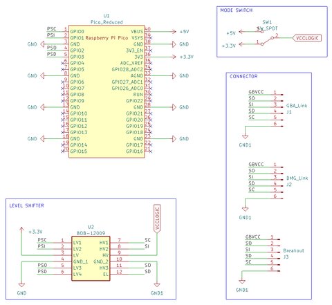
The firmware uses the RP2040 PIO to communicate with the Game Boy link port. This page documents pin assignments for DIY builders.
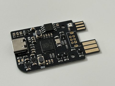
| Source | Link |
|---|---|
| GB-Link USB V2 (assembled) | Crowd Supply |
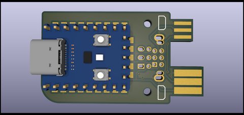
| Pico PCB (DIY) | game-boy-pico-link-board |
| Pico Zero PCB (DIY) | game-boy-zero-link-board |
Connect the link cable wires to the RP2040 as follows:
| Game Boy Signal | RP2040 Pin |
|---|---|
| SCK (Clock) | GP0 |
| SIN (Data In) | GP1 |
| SOUT (Data Out) | GP2 |
| SD (Chip Select) | GP3 (GBA cable) / GP4 (GBC cable) |
| GND | Ground |
| Function | Pin | Usage |
|---|---|---|
| Voltage 3.3V | GP11 | Pull low for 3.3V |
| Voltage 5V | GP12 | Pull low for 5V |
| WS2812 LED | GP16 | NeoPixel status indicator |
Warning: Do not pull both GP11 and GP12 low at the same time. This can damage the board.
| Cable Type | SD Pin | Supported Modes |
|---|---|---|
| OEM GBA Link Cable | GP3 | GBA modes only |
| Generic GBC Link Cable | GP4 (GBA mode) | All GBA and GB modes |
The firmware auto-detects cable type at mode selection time.
From the product page:
Works with FPGA consoles that expose a physical link port:
Does not work with software emulators or handhelds without a link port.